Case Studies Manufacturing · Plastics

In-Line Vision Inspection for Injection Moulding

Flash, short shots and sink marks escape the eye at line pace. 3D profile plus 2D imaging decide after each cycle and feed defect data back to process settings.

2026-11-03 1 views
In-Line Vision Inspection for Injection Moulding
Defect types|Flash, short shot, sink Scan method|3D profile Decision|2D plus 3D fused Footprint|Standalone cell

Project Background

Typical moulding defects are flash, flow marks, short shots, delamination and sink marks. They are hard to see on low-contrast surfaces, translucent material or complex geometry, and manual visual inspection at line pace amounts to sampling rather than full inspection.

The client relied on mechanical sensors plus human eyes. Sensors only confirm presence, operators only see the outside, and deep cavities and raised edges, where defects concentrate, were effectively unchecked.

Products Used

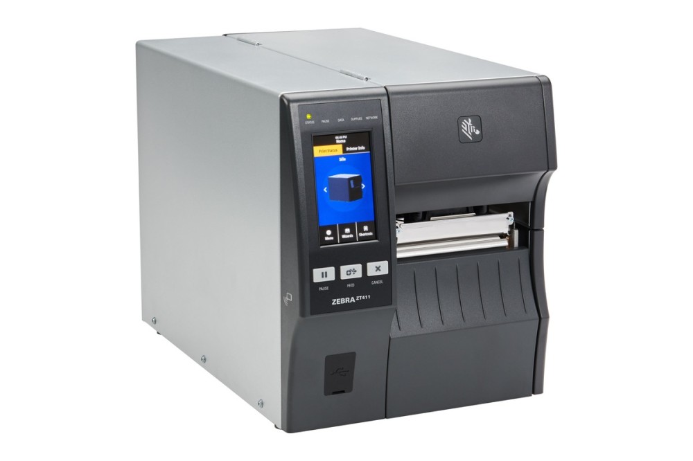
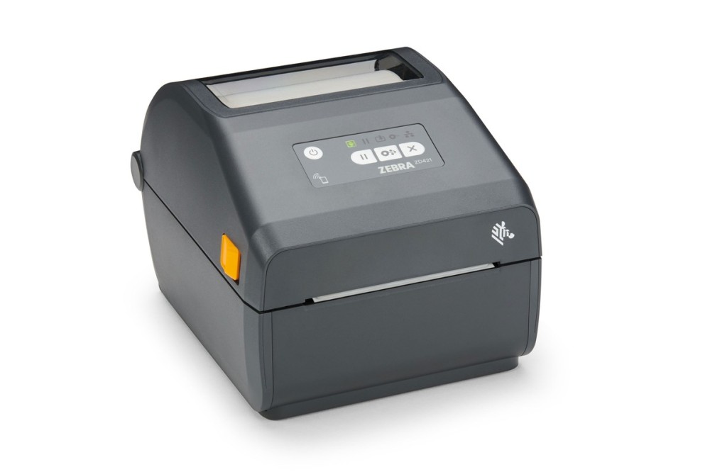
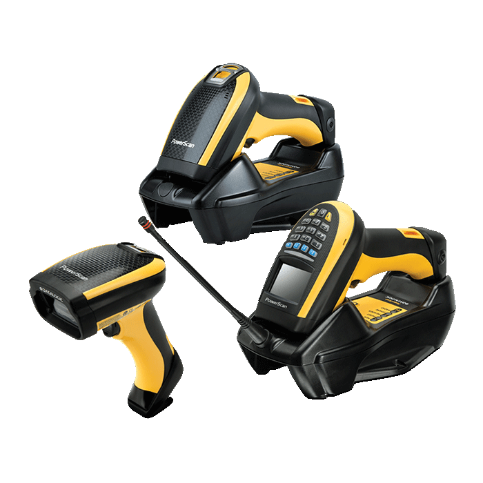
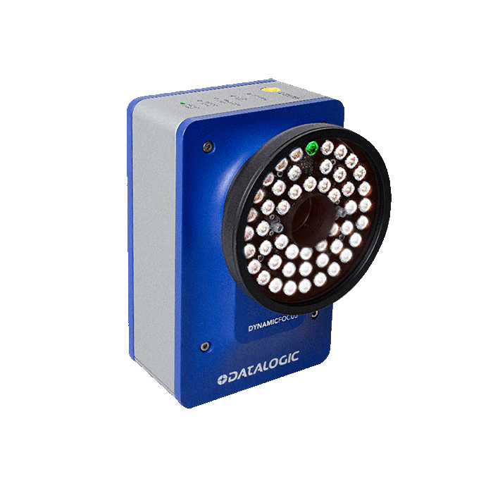
Equipment and consumables commonly used in this scenario, configurable to your site.

Solutions

Based on the site conditions, we delivered the following custom solution.

The cell sits after the tool

The inspection cell stands beside the moulding machine and the part moves into it straight after ejection, so machine time is not consumed. A dual-camera single-laser 3D profile sensor covers the surface transitions on complex parts and reduces the scan gaps caused by optical occlusion, so deep cavities and raised edges are fully modelled.

2D and 3D decide together

3D data carries dimensions and form, 2D images carry appearance and colour variation, and the decision is made after fusion. Flash, a defect of very small height difference, is almost invisible to a 2D camera alone; with profile data the criterion becomes measurable.

Defect data feeds back to the process

Results are recorded by defect type, position and time and compared against machine parameters. It becomes visible whether a defect class appears after a tool change or correlates with mould temperature and hold pressure. That is what moves inspection from sorting out bad parts to producing fewer of them.

Why this configuration

Moulded parts carry no code, and what has to be judged is surface defect and assembly completeness, so the choice is vision rather than decoding. Lighting follows the defect: a low-angle ring for scratches and sink marks, backlight for missing or wrong parts where the silhouette is what matters.

Triggering is by photoelectric sensor rather than a timer, so a frame is taken only when a part is present and neither empty shots nor missed parts occur. Rejection is by air blow, completed before the next index so the station does not lose cycle time.


Implementation Highlights

Key steps and engineering details from the deployment.

Standalone cell, no impact on moulding cycle time Dual-camera single-laser design reduces gaps on complex parts 3D dimensional and 2D appearance results fused into one decision Operator interface set by parameters and tolerances, no programming required Defects counted by type and position for process analysis PLC communication triggers sorting on the decision

Related Case Studies

Similar projects in the same industry or application.

Need a Similar Implementation?

From device selection and label matching to system integration, tell us what you need and an engineer will prepare a plan.

Call Us WeChat Get a Quote